UPM315

DIN 96x96 LCD power meter connectable to MFC150 Rogowski coil

UPM315 LCD Power Meter to MFC150

Highlights

  • DIN 96 for new or retrofit panels
  • Highly sofisticated power meter providing advanced
  • functionality features
  • Large graphic LCD display with excellent visibility
  • Up to two plug-in options
  • THD even, odd and individual FFT harmonic analysis up to 50th order
  • Power and current demand calculation
  • On-board memory up to 2 MB
  • Programmable Min/Max & energy data logging
  • Event and alarm recording, waveform capture, waveform display, phasor diagrams, historical trending, time-of-use and more...

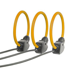
The UPM315 with option "RGW" can be combined to the MFC150 Rogowski coil.


Applications

  • Switchboards, gensets, motor control centers, etc.
  • Power monitoring & control systems
  • Individual machine load monitoring
  • Power demand analysis and management
  • Harmonics monitoring
  • Remote metering and cost allocation.

Available Configurations

Measurements
  • Single-phase and three-phase 3-wire or 4-wire unbalanced load operation.
  • Direct measurement up to 600 (750) VAC.
  • Programmable 1A / 5A current full scale.
  • True rms metering provides accurate measurement even for distorted waveform.
  • Fully bidirectional, four-quadrant readings. 10 energy counters are available, the apparent energy is splitted in four counters: import lagging, import leading, export lagging, export leading.
  • Volts, Amps, Power, PF, Frequency, Energy, Min/Max values, Demand, Harmonics, etc. The full version instrument provides more than 600 measured/calculated parameters and shows on the LCD more than 35 graphical pages.
  • Individual & total harmonic distortion for voltage and current up to the 50th order. The harmonic content is represented like even, odd and total.
  • Advanced waveform capture function. The instrument can store, after a trigger, up to 200 waves with a resolution from 16 to 128 samples (depending on the number of waveforms). The trigger can be programmed on a digital output change, on a set point crossing or the capture can be started from the keypad. The stored waweform is downloadable through the communication port.
On-board memory
  • 2 MB non-volatile memory for data storage.
  • Programmable start/stop time of recordings.
  • Wraparound or Fill (FIFO/Stack) selectable recording mode.
  • Min/Avg/Max logging every 1, 5, 10, 15, 30, 60 minutes, programmable up to 8 selectable parameters.
  • Total and daily energy consumption recording. The consumption of more than 300 days is recorded.
  • Time-of-Use (TOU) programmable data recording. The TOU function stores the energy consumption in different registers according the programmed time-scheme. A group of 200 registers gives the situation of the previous and current day, and of the previous and current month. This feature is designed to t different tariff structures, according to the number of TOU included in instrument:
    • 5 TOU: it is possible to program up to 120 daily tariff schedules containing up to 5 tariffs and 15 tariff changes. Each schedule can be assigned to the days of the week and months as requested. Up to 20 holidays can be assigned to the lowest tariff. Moreover, the holiday function can be enabled or disabled. A diagnostic algorithm checks and noti es any setup overlapping.
    • 4 TOU: it is possible to program up to 10 daily tariff schedules containing up to 4 tariffs and 8 tariff changes. Each schedule can be assigned to the days of the week and months as requested. Up to 20 holidays can be assigned to the lowest tariff. A diagnostic algorithm checks and noti es any setup overlapping.
  • In case of more than one electricity supplier, it is possible to start from the recorded demand values instead of the daily ones. Each value is recorded with date and time and can be exported for example, in .xls format. This allows to create a exible map that considers the different electricity suppliers. The DMD value is the AVG value (see programmable recordings).
  • Event, alarm and digital outputs ON/OFF recording. The instrument records the status change of 8 programmable set points, the digital outputs ON/OFF and the instrument supply ON/OFF. All the events are integrated by date and time reference.
Modularity
  • Two slots for optional AO plug-in boards (up to no. 4 analog outputs 0-20 or 4-20 mA).
  • The compact DIN96 instrument allows to t the requirements of new installations as well as retro t applications.
Graphics
  • The excellent graphical display performs clear graphical representations allowing an immediate comprehension of the measured parameters. The voltage and current waveforms, the harmonic spectrum and the phasor diagrams are displayed. Moreover 6 measured values can be represented as a graphical trend on the display. The scale of the trend can be selected between 15 min, 1 hour, 1 day and 1 month.
Communication
  • Both RS232 and RS485 selectable by dip-switches.
  • Selectable MODBUS or A2 ASCII protocol.
  • Communication speed programmable up to 57600 bps
  • Optional Pro bus interface.

Inputs & outputs
  • Two digital outputs for energy pulsing or for alarm tripping.
  • Up to 4 analog outputs 0-20 or 4-20 mA.
  • On request input for Rogowski coils.
Other
  • Real time clock with battery backup.
  • Calculation of capacitor bank value for PF compensation.
  • No. 1 programmable user page with 6 parameters selected among measured values.
  • Five alphanumeric character password to avoid unauthorized setup access.
  • Downloadable rmware via serial port.

Power supply

Rated voltage: 65...250 VAC / 90...250 VDC on request 19...60 VDC on request
Consumption: 5 VA max

Voltage inputs

Maximum measurable voltage: 600 (750) VAC max L-L
Input impedance: ›1.3 MOhm
Burden: 0.15 VA max per phase
Frequency: 45 - 65 Hz

Current inputs

Rated current (Ib): 1 / 5 programmable
Min / max measurable current: 20 mA / 7 ARMS
Maximum overload: 10A continuous - 100A for 1 sec.
Input impedance: 0,02 Ohm approximately
Burden: 0,5 VA per phase
Insulation voltage: 150 VAC max between phases
Rogowski input: 200A·49995 A on request

Typical accuracy

Voltage: ±0.1% reading ±0.03% full scale
Current: ±0.1% reading ±0.05% full scale
Active power: ±0.5% reading ±0.1% full scale (PF=1)
Power factor: 1% reading (0.5 inductive - 0.8 capacitive)
Active energy: 1% reading (0.5 inductive - 0.8 capacitive)
Frequency: ±0.05% reading ±2 digits from 45 to 65 Hz

Display and operating controls

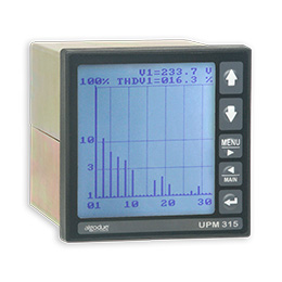
Display: backlighted graphic LCD display, 160 x 144 dots
Keypad: 5 push-buttons

Data Memory

Type: on-board non-volatile FLASH, 2 MB

Communication port

Type: 1 selectable RS232 or RS485, optoisolated
Baud rate: programmable from 300 to 57600 bps
Protocols: A2 ASCII, MODBUS

Real Time Clock

Type: with battery backup
Accuracy: ± 30 ppm

Digital outputs

Type: 2 optoisolated (50V - 300 mADC)

Environmental conditions

Operating temperature: from -15 °C to +60 °C
Storage temperature: from -25 °C to +75 °C
Relative humidity: 80% max. without condensation

Mechanical characteristics

Terminals: EU standard pluggable terminals
Size / weight: 96x96x130 mm / 750 g

Standard compliance

Safety: 73/23/EEC and 93/68/EEC directives, EN 61010.1 safety standard
EMC: 89/366/EEC directive and following modifications 93/31/EEC and 93/68/EEC, EN50081-2, EN50082-2, EN61326/A1